Привет народ, хочу рассказать про TMC2209 BIGTREETECH v1.2 UART, ramps 1.4, arduino DUE и klipper, возможно эта информация будет кому нибудь полезна:
Для начала расскажу про свое оборудование:
1. Ramps 1.4 переделанный под arduino due + отдельная силовая плата с оптической развязкой...
2. Дисплей
RepRapDiscount Smart Controller
3. Кинематика каретки h-bot, привод стола через ходовой винт с шагом 8 мм
4. Управляет всем этим orangepi pc+ под управлением armbian и octoprint//

Спойлер
Предыстория
Недавно достались мне TMC2209 BIGTREETECH v1.2 UART
Возникла мысль сделать стол с автоматической калибровкой (гугли stallGuard), но из за недостаточной жесткости механизма перемещения головки, а также из за привода стола (ходовой винт) эта затея потерпела неудачу.
Ну и судя по отзывам в сети, народ не рекомендует делать калибровку стола с использованием технологии stallGuard
Раньше ипользовал Repetier но т.к. он не поддерживает tmc2209 в режиме UART - решил перейти на Klipper...
Спойлер
Проблемы
1. Klipper позволяет прошить due через programming port(repetier у меня работал только через programming port), но не хочет подключаться к плате после прошивки..
- проблему удалось решить подключив DUE через
Native USB...
2.
Klipper требует доработки китайской arduino due
Решил применить TMC2209 в режиме UART на оси X и Y с применением технологии stallGuard (без концевиков)
Спойлер
TMC2209 BIGTREETECH v1.2 UART
1. Arduino due имеет 4 uart порта
- 0 порт отвечает за связь (выводы ar0, ar1)
- 2 порт занят дисплеем
- остаются 1 и 3 порты, это соответственно ar14, ar15 и ar18, ar19
На 1 и 3 порты и будем вешать связь с драйверами двигателей Х и Y.
2. Чтобы реализовать виртуальные концевики нужно ножку diag tmc2209 подсоединить к due (см. параметр diag_pin в printer.cfg) и соответственно ногу UART присоединить к одному из портов UART due (к ноге rx)
Никаких переходников с резистором (как в marlin) паять не нужно, просто напрямую 1 проводом подсоединяем ногу UART TMC2209 к ноге RX due, и ногу DIAG TMC2209 на свободную ногу контроллера.
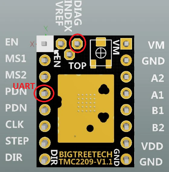
- tmc2209-BIGTREETECH-v1.1-pin-map
- tmc2209_pin_map.png (285.41 КБ) 5836 просмотров
Изображение подходит и к версии 1.2 от BIGTREETECH
Положение порта UART может меняться,
см. раздел 8.1 мануала
п.с в разделе 8.2 показана схема подключения драйвера к контроллеру (эта схема актуальна для Marlin 2.0) схема для klipper ниже:
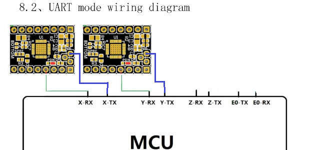
- Подключение к Due
- tmc2209_connection.png (111.68 КБ) 5836 просмотров
Синий провод это подключение ноги DIAG TMC2209 к контроллеру (нужно для работы виртуальных концевиков, в работе UART не учавствует, подкючать к пину Tx не обязательно, можно к любому другому свободному)
Итак, в моем случае подключение выглядит так:
Двигатель Х
Двигатель Y
Ну и еще остается место для 2 концевиков, ниже приведу полный конфиг Klipper...
Собственно на этом подключение закончено...
Настройка klipper на работу с TMC 2209
Спойлер
Для работы TMC 2209 в режиме Uart в Klipper я указал следующие параметры(на примере двигателя X, для Y полностью аналогично, см. полный конфиг ниже)
1. вводим секцию [tmc2209 stepper_x]
Код: Выделить всё
[tmc2209 stepper_x]
uart_pin: ar15			#Y-max-endstop
microsteps: 16
run_current: 0.4
hold_current: 0.3
stealthchop_threshold: 100
interpolate: true
driver_SGTHRS: 75		# чувствительность [0:255], 0-наименее чувствительный
diag_pin: ^ar14		# нога контроллера к которой подключен DIAG вывод TMC2209 (см. изображение выше)
sense_resistor: 0.110
Особо стоит отметить параметр driver_SGTHRS это чувствительность драйвера - "чувствительность виртуального концевика", настраивается индивидуально(0- выключено, 255 - очень чувствительный).
2. В разделе [stepper_x]
Код: Выделить всё
[stepper_x]
step_pin: ar54
dir_pin: ar55
enable_pin: !ar38
step_distance: 0.0125
[b]endstop_pin: tmc2209_stepper_x:virtual_endstop[/b]
position_endstop: 0
position_min: 0
position_max: 210
homing_speed: 50
homing_positive_dir: false
В общем то на это настройка звершена...
И можно пробовать...
Ниже приведен мой полный рабочий конфиг
Спойлер
printer.cfg
Код: Выделить всё
# This file serves as documentation for config parameters. One may
# copy and edit this file to configure a new cartesian style
# printer. For delta style printers, see the "example-delta.cfg"
# file. For corexy/h-bot style printers, see the "example-corexy.cfg"
# file. Only common config sections are described here - see the
# "example-extras.cfg" file for configuring less common devices.

# DO NOT COPY THIS FILE WITHOUT CAREFULLY READING AND UPDATING IT
# FIRST. Incorrectly configured parameters may cause damage.

# A note on pin names: pins may be configured with a hardware name
# (such as "PA4") or with an Arduino alias name (such as "ar29" or
# "analog3"). In order to use Arduino names, the pin_map variable in
# the mcu section must be present and have a value of "arduino". Pin
# names may be preceded by an '!' to indicate that a reverse polarity
# should be used (eg, trigger on low instead of high). Input pins may
# be preceded by a '^' to indicate that a hardware pull-up resistor
# should be enabled for the pin. If the micro-controller supports
# pull-down resistors then an input pin may alternatively be preceded
# by a '~'.

# Micro-controller information.
[mcu]
serial: /dev/serial/by-id/usb-Klipper_sam3x8e_20312051503038383232303231303139-if00
pin_map: arduino
baud: 115200

[tmc2209 stepper_x]
uart_pin: ar15			#Y-max-endstop
microsteps: 16
run_current: 0.4
hold_current: 0.3
stealthchop_threshold: 100
interpolate: true
driver_SGTHRS: 75		# чувствительность [0:255], 0-наименее чувствительный
diag_pin: ^ar14
sense_resistor: 0.110

[tmc2209 stepper_y]
uart_pin: ar19			#Z-max-endstop
microsteps: 16
run_current: 0.4
hold_current: 0.3
stealthchop_threshold: 100
interpolate: true
driver_SGTHRS: 75		# чувствительность [0:255], 0-наименее чувствительный
diag_pin: ^ar18
sense_resistor: 0.110

#[probe]
#pin: tmc2209_stepper_z:virtual_endstop
#z_offset: 0

# The stepper_x section is used to describe the stepper controlling
# the X axis in a cartesian robot.
[stepper_x]
step_pin: ar54
dir_pin: ar55
enable_pin: !ar38
step_distance: 0.0125
endstop_pin: tmc2209_stepper_x:virtual_endstop
position_endstop: 0
position_min: 0
position_max: 210
homing_speed: 50
homing_positive_dir: false


# The stepper_y section is used to describe the stepper controlling
# the Y axis in a cartesian robot. It has the same settings as the
# stepper_x section.
[stepper_y]
step_pin: ar60
dir_pin: !ar61
enable_pin: !ar56
step_distance: 0.0125

#endstop_pin: ^!ar3 # x-min
endstop_pin: tmc2209_stepper_y:virtual_endstop

position_endstop: 0
position_max: 210
homing_speed: 50
homing_positive_dir: false

# The stepper_z section is used to describe the stepper controlling
# the Z axis in a cartesian robot. It has the same settings as the
# stepper_x section.
[stepper_z]
step_pin: ar46
dir_pin: !ar48
enable_pin: !ar62
step_distance: 0.000625
endstop_pin: ^ar2
#endstop_pin: tmc2209_stepper_z:virtual_endstop
#endstop_pin:^ar2
position_endstop: 209.7
position_min: 0
position_max: 210.7
homing_speed: 50


[adc_temperature my_thermistor]
temperature1: 20
resistance1: 94000
temperature2: 50
resistance2: 36800
temperature3: 70
resistance3: 15400
temperature4: 90
resistance4: 8270
temperature5: 100
resistance5: 6920
temperature6: 110
resistance6: 5690
temperature7: 120
resistance7: 4990
temperature8: 130
resistance8: 4285
temperature9: 140
resistance9: 3700
temperature10: 150
resistance10: 3370
temperature11: 170
resistance11: 2840
temperature12: 190
resistance12: 2555
temperature13: 210
resistance13: 2410
temperature14: 230
resistance14: 2300
temperature15: 250
resistance15: 2220

# The extruder section is used to describe both the stepper
# controlling the printer extruder and the heater parameters for the
# nozzle. The stepper configuration has the same settings as the
# stepper_x section and the heater configuration has the same settings
# as the heater_bed section (described below).
[extruder]
step_pin: ar26
dir_pin: !ar28
enable_pin: !ar24
step_distance: 0.0056124923077
nozzle_diameter: 0.400
#   Diameter of the nozzle orifice (in mm). This parameter must be
#   provided.
filament_diameter: 1.7500
#   The nominal diameter of the raw filament (in mm) as it enters the
#   extruder. This parameter must be provided.
#max_extrude_cross_section:
#   Maximum area (in mm^2) of an extrusion cross section (eg,
#   extrusion width multiplied by layer height). This setting prevents
#   excessive amounts of extrusion during relatively small XY moves.
#   If a move requests an extrusion rate that would exceed this value
#   it will cause an error to be returned. The default is: 4.0 *
#   nozzle_diameter^2
#instantaneous_corner_velocity: 1.000
#   The maximum instantaneous velocity change (in mm/s) of the
#   extruder during the junction of two moves. The default is 1mm/s.
#max_extrude_only_distance: 50.0
#   Maximum length (in mm of raw filament) that a retraction or
#   extrude-only move may have. If a retraction or extrude-only move
#   requests a distance greater than this value it will cause an error
#   to be returned. The default is 50mm.
#max_extrude_only_velocity:
#max_extrude_only_accel:
#   Maximum velocity (in mm/s) and acceleration (in mm/s^2) of the
#   extruder motor for retractions and extrude-only moves. These
#   settings do not have any impact on normal printing moves. If not
#   specified then they are calculated to match the limit an XY
#   printing move with a cross section of 4.0*nozzle_diameter^2 would
#   have.
#pressure_advance: 0.0
#   The amount of raw filament to push into the extruder during
#   extruder acceleration. An equal amount of filament is retracted
#   during deceleration. It is measured in millimeters per
#   millimeter/second. The default is 0, which disables pressure
#   advance.
#pressure_advance_smooth_time: 0.040
#   A time range (in seconds) to use when calculating the average
#   extruder velocity for pressure advance. A larger value results in
#   smoother extruder movements. This parameter may not exceed 200ms.
#   This setting only applies if pressure_advance is non-zero. The
#   default is 0.040 (40 milliseconds).
#
# The remaining variables describe the extruder heater.
heater_pin: ar59
#   PWM output pin controlling the heater. This parameter must be
#   provided.
#max_power: 1.0
#   The maximum power (expressed as a value from 0.0 to 1.0) that the
#   heater_pin may be set to. The value 1.0 allows the pin to be set
#   fully enabled for extended periods, while a value of 0.5 would
#   allow the pin to be enabled for no more than half the time. This
#   setting may be used to limit the total power output (over extended
#   periods) to the heater. The default is 1.0.
sensor_type: my_thermistor
#   Type of sensor - common thermistors are "EPCOS 100K B57560G104F",
#   "ATC Semitec 104GT-2", "NTC 100K beta 3950", "Honeywell 100K
#   135-104LAG-J01", and "NTC 100K MGB18-104F39050L32". See the
#   example-extras.cfg file for other sensors. This parameter must be
#   provided.
sensor_pin: analog9
#   Analog input pin connected to the sensor. This parameter must be
#   provided.
pullup_resistor: 4700
#   The resistance (in ohms) of the pullup attached to the thermistor.
#   This parameter is only valid when the sensor is a thermistor. The
#   default is 4700 ohms.
#inline_resistor: 4700
#   The resistance (in ohms) of an extra (not heat varying) resistor
#   that is placed inline with the thermistor. It is rare to set this.
#   This parameter is only valid when the sensor is a thermistor. The
#   default is 0 ohms.
#smooth_time: 2.0
#   A time value (in seconds) over which temperature measurements will
#   be smoothed to reduce the impact of measurement noise. The default
#   is 2 seconds.
control: pid
#   Control algorithm (either pid or watermark). This parameter must
#   be provided.
pid_Kp: 34.542
#   Kp is the "proportional" constant for the pid. This parameter must
#   be provided for PID heaters.
pid_Ki: 1.599
#   Ki is the "integral" constant for the pid. This parameter must be
#   provided for PID heaters.
pid_Kd: 186.528
#   Kd is the "derivative" constant for the pid. This parameter must
#   be provided for PID heaters.
#pid_integral_max:
#   The maximum "windup" the integral term may accumulate. The default
#   is to use the same value as max_power.
#pwm_cycle_time: 0.100
#   Time in seconds for each software PWM cycle of the heater. It is
#   not recommended to set this unless there is an electrical
#   requirement to switch the heater faster than 10 times a second.
#   The default is 0.100 seconds.
#min_extrude_temp: 170
#   The minimum temperature (in Celsius) at which extruder move
#   commands may be issued. The default is 170 Celsius.
min_temp: 0
max_temp: 235
#   The maximum range of valid temperatures (in Celsius) that the
#   heater must remain within. This controls a safety feature
#   implemented in the micro-controller code - should the measured
#   temperature ever fall outside this range then the micro-controller
#   will go into a shutdown state. This check can help detect some
#   heater and sensor hardware failures. Set this range just wide
#   enough so that reasonable temperatures do not result in an
#   error. These parameters must be provided.

# The heater_bed section describes a heated bed (if present - omit
# section if not present).
[heater_bed]
heater_pin: ar66
sensor_type: EPCOS 100K B57560G104F
sensor_pin: analog10
control: watermark
#max_delta: 2.0
#   On 'watermark' controlled heaters this is the number of degrees in
#   Celsius above the target temperature before disabling the heater
#   as well as the number of degrees below the target before
#   re-enabling the heater. The default is 2 degrees Celsius.
min_temp: 0
max_temp: 110

# Print cooling fan (omit section if fan not present).
[fan]
pin: ar9
#   PWM output pin controlling the fan. This parameter must be
#   provided.
#max_power: 1.0
#   The maximum power (expressed as a value from 0.0 to 1.0) that the
#   pin may be set to. The value 1.0 allows the pin to be set fully
#   enabled for extended periods, while a value of 0.5 would allow the
#   pin to be enabled for no more than half the time. This setting may
#   be used to limit the total power output (over extended periods) to
#   the fan. If this value is less than 1.0 then fan speed requests
#   will be scaled between zero and max_power (for example, if
#   max_power is .9 and a fan speed of 80% is requested then the fan
#   power will be set to 72%). The default is 1.0.
#shutdown_speed: 0
#   The desired fan speed (expressed as a value from 0.0 to 1.0) if
#   the micro-controller software enters an error state. The default
#   is 0.
#cycle_time: 0.010
#   The amount of time (in seconds) for each PWM power cycle to the
#   fan. It is recommended this be 10 milliseconds or greater when
#   using software based PWM. The default is 0.010 seconds.
#hardware_pwm: False
#   Enable this to use hardware PWM instead of software PWM. Most fans
#   do not work well with hardware PWM, so it is not recommended to
#   enable this unless there is an electrical requirement to switch at
#   very high speeds. When using hardware PWM the actual cycle time is
#   constrained by the implementation and may be significantly
#   different than the requested cycle_time. The default is False.
#kick_start_time: 0.100
#   Time (in seconds) to run the fan at full speed when either first
#   enabling or increasing it by more than 50% (helps get the fan spinning).
#   The default is 0.100 seconds.
#off_below: 0.0
#   The minimum input speed which will power the fan (expressed as a
#   value from 0.0 to 1.0). When a speed lower than off_below is
#   requested the fan will instead be turned off. This setting may be
#   used to prevent fan stalls and to ensure kick starts are
#   effective. The default is 0.0.
#
#   This setting should be recalibrated whenever max_power is adjusted.
#   To calibrate this setting, start with off_below set to 0.0 and the
#   fan spinning. Gradually lower the fan speed to determine the lowest
#   input speed which reliably drives the fan without stalls. Set
#   off_below to the duty cycle corresponding to this value (for
#   example, 12% -> 0.12) or slightly higher.


[printer]
kinematics: corexy
#   This option must be "cartesian" for cartesian printers.
max_velocity: 500
#   Maximum velocity (in mm/s) of the toolhead (relative to the
#   print). This parameter must be specified.
max_accel: 3000
#   Maximum acceleration (in mm/s^2) of the toolhead (relative to the
#   print). This parameter must be specified.
#max_accel_to_decel:
#   A pseudo acceleration (in mm/s^2) controlling how fast the
#   toolhead may go from acceleration to deceleration. It is used to
#   reduce the top speed of short zig-zag moves (and thus reduce
#   printer vibration from these moves). The default is half of
#   max_accel.
max_z_velocity: 25
#   For cartesian printers this sets the maximum velocity (in mm/s) of
#   movement along the z axis. This setting can be used to restrict
#   the maximum speed of the z stepper motor on cartesian
#   printers. The default is to use max_velocity for max_z_velocity.
max_z_accel: 30
#   For cartesian printers this sets the maximum acceleration (in
#   mm/s^2) of movement along the z axis. It limits the acceleration
#   of the z stepper motor on cartesian printers. The default is to
#   use max_accel for max_z_accel.
#square_corner_velocity: 5.0
#   The maximum velocity (in mm/s) that the toolhead may travel a 90
#   degree corner at. A non-zero value can reduce changes in extruder
#   flow rates by enabling instantaneous velocity changes of the
#   toolhead during cornering. This value configures the internal
#   centripetal velocity cornering algorithm; corners with angles
#   larger than 90 degrees will have a higher cornering velocity while
#   corners with angles less than 90 degrees will have a lower
#   cornering velocity. If this is set to zero then the toolhead will
#   decelerate to zero at each corner. The default is 5mm/s.

[display]
lcd_type: hd44780
rs_pin: ar16
e_pin: ar17
d4_pin: ar23
d5_pin: ar25
d6_pin: ar27
d7_pin: ar29
encoder_pins: ^ar33, ^ar31
click_pin: ^!ar35
kill_pin: ^!ar41

[virtual_sdcard]
path: /home/octoprint/.octoprint/uploads

[homing_override]
gcode:
    G28 Z
    G28 X
    G28 Y

#[gcode_macro START_PRINT]
#default_parameter_BED_TEMP: 55
#default_parameter_EXTRUDER_TEMP: 215
#gcode:
#    CLEAR_PAUSE
#    M140 S{BED_TEMP}
#    M190 S{BED_TEMP}
#    M109 S{EXTRUDER_TEMP}
#    G90
#    G28
#    G1 X50 Y150 F2000
#    G1 Z5 F1000
#
#
#[gcode_macro END_PRINT]
#gcode:
#    TURN_OFF_HEATERS
#    M106 S0
#    G91
#    G10
#    G1 Z20 X-20 Y-20
#    G90
#    M84


## G10/G11 ###
#[firmware_retraction]
#retract_length: 5.8
#retract_speed: 80
#nretract_extra_length: 0
#nretract_speed: 80
# Looking for more options? Check the example-extras.cfg file.
Спойлер
Работа с TMC 2209 в Klipper
После включения принтера можно проверить подключение драйверов:
DUMP_TMC stepper=stepper_x
DUMP_TMC stepper=stepper_y
Консоль должна выдать что-то похожее:
Код: Выделить всё
Send: DUMP_TMC stepper=stepper_y
Recv: // ========== Write-only registers ==========
Recv: // IHOLD_IRUN: 00080c09 IHOLD=9 IRUN=12 IHOLDDELAY=8
Recv: // TPWMTHRS:   0000005e TPWMTHRS=94
Recv: // TPOWERDOWN: 00000014 TPOWERDOWN=20
Recv: // SGTHRS:     0000004b SGTHRS=75
Recv: // ========== Queried registers ==========
Recv: // GCONF:      000001c0 pdn_disable=1 mstep_reg_select=1 multistep_filt=1
Recv: // GSTAT:      00000001 reset=1
Recv: // IFCNT:      00000007 IFCNT=7
Recv: // OTP_READ:   0000000c OTP_FCLKTRIM=12
Recv: // IOIN:       21000041 ENN=1 PDN_UART=1 VERSION=0x21
Recv: // FACTORY_CONF: 0000000c FCLKTRIM=12
Recv: // TSTEP:      000fffff TSTEP=1048575
Recv: // MSCNT:      00000028 MSCNT=40
Recv: // MSCURACT:   00ef003c CUR_A=60 CUR_B=239
Recv: // CHOPCONF:   14030053 toff=3 hstrt=5 TBL=2 vsense=1 MRES=4(16usteps) intpol=1
Recv: // DRV_STATUS: c0090000 CS_ACTUAL=9 stealth=1 stst=1
Recv: // PWMCONF:    c80d0e24 PWM_OFS=36 PWM_GRAD=14 pwm_freq=1 pwm_autoscale=1 pwm_autograd=1 PWM_REG=8 PWM_LIM=12
Recv: // PWM_SCALE:  0000000b PWM_SCALE_SUM=11
Recv: // PWM_AUTO:   000e0024 PWM_OFS_AUTO=36 PWM_GRAD_AUTO=14
Recv: // SG_RESULT:  00000000
Recv: ok
Подбираем свой driver_SGTHRS (0- выключено, 255 - очень чувствительный), и радуемся
Полезные ссылки
G-Code Klipper
Документация от Bigtreetech на tmc2209v2
п.с. Если гдето ошибся или указал неточно, поправьте, буду благодарен

п.п.с Всем бобра
